Kai Tak Stormwater Transfer Scheme
Investigators:
|
Collaborators:
|
Introduction
The Kai Tak Stormwater Transfer Scheme (KTTS) is an essential component
of the West Kowloon Drainage Improvement -- Stage 2 Project that will be
implemented to solve the flooding problem in Mongkok - a congested and
densely populated district of the Hong Kong Special Administration
Region of China. Under existing conditions, the stormwater runoff from
upstream is conveyed in a steep box culvert (1:64 bed slope) underneath
Waterloo Road. For the design scenario, a maximum of 65 m3/s flows in
the Waterloo Road culvert to join with the downstream Boundary Street
nullah which flows into the storm sewer system in the Mongkok area. In
the past decade, due to increased urbanisation and stormwater runoff,
the existing urban drainage system failed to cope with severe floods;
there are many flooding `black spots' in Mongkok. Rather than digging up
roads and widening/adding existing drains, which would be highly
disruptive to the heavy traffic and interfere with numerous existing
underground structures and utilities (and needing long construction
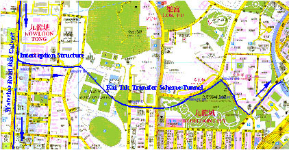
times), an upstream flow diversion scheme has been devised. The Kai Tak
Stormwater Transfer Scheme (KTTS) aims to divert about two-thirds of the
design flow from the Waterloo Road culvert into a 4 m diameter
underground tunnel (the Kai Tak Transfer Tunnel) by means of an
interception structure, thus relieving downstream flood prone areas of
the stormwater load. Together with the Tai Hang Tung Storage Tank
Scheme, this innovative urban flood control scheme will reduce the
length of drains required with large financial savings. The success of
the scheme depends on the ability of the interception structure to
divert the desired flow in a hydraulically satisfactory manner for all
flows.
|
|
|
The planning route of the KTTS tunnel |
Practical constraints dictate that the interception structure must be
designed to intercept the required flow from the Waterloo Road into the
tunnel underneath Hereford Road; it needs to achieve a drop of 6.4 m
within a distance of about 40m and maintain a 1.5m clearance from an
existing sewer main and a freshwater supply main running parallel to (at
different elevation) the Waterloo Road culvert. A 1:25 undistorted
Froude scale hydraulic model has been designed and constructed to study
the hydraulics of the complicated three-dimensional diversion flows and
the design of the interception structure.
|
|
|
Observed spillway flow and subsequent jump in interception structure |
|
A second hydraulic jump is also observed on the Waeterloo Road flow downstream of the diversion; this jump appears to arrest all the hydraulic control from downstream. In addition, a tornado vortex emanating from the outer corner of the interception structure (Point S) is clearly observed.
|
 |
|
Observed tornado vortex in Waterloo Road flow downstream of interception structure |
Extensive model tests have been performed for the entire range of gravity and pressurized flows. The results show the flow in the interception and transition structure is highly turbulent and characterised by jet impingement, air entrainment and mixing, and energy dissipation. The required flow diversion of about 60-70 percent and stable flow conditions can be achieved with the final design as shown, with the following characteristics:
-
The interception structure consists of a relatively straight spillway chute (with maximum slope of 23.5 degrees) accounting for most of the drop in elevation, and a transitional bend leading into a 4m square tunnel; gradual transitions and regular cross-section shapes are maintained as far as possible.
The interior of the interception structure is partitioned by a splitter wall (with a cutwater sharp edge facing the oncoming flow at about 17 degrees) into two chambers to reduce cross-waves. Two air vents are provided at the top of the structure. -
The downstream corner of the entrance to the interception structure in the Waterloo Road culvert is streamlined to minimize flow separation and formation of tornado vortices.
-
Two rows of stilling blocks are placed in tandem at the downstream end of the square tunnel to stabilize and localize the hydraulic jump.